Rockwell Automation is a leader in automation. The company's domain expertise is built on decades of work across all industries and all regions of the world. They understand the factory floor and the business models that make it the most productive - and are fluent in the real-world production challenges customers face. Rockwell Automation also knows how to identify critical data, what it means and how to make it useful to industrial and enterprise users.
Rely on Rockwell Automation to provide a full scope of capabilities to deliver the solutions and services you need now and in the future.
Pneumatic cylinders are highly varied in their construction and execution, making them difficult to select when you don’t understand your requirements. I won’t pretend that application isn’t the most important deciding factor, but the same can be said of any fluid power actuator. This guide provides all the information you need to select the pneumatic cylinder design best suited to your machine.
First and foremost, I recommend you first read A Designer’s Guide to Cylinders which covers a lot of technical but general information related to cylinder selection. This article is to elucidate the specific nature of pneumatic cylinders to help you refine your selection amongst the myriad standardized and custom solutions offered by manufacturers.
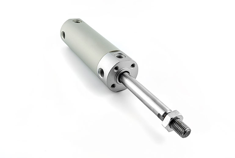
Figure 1. Most pneumatic cylinders are available with stainless steel or anodized aluminum construction.
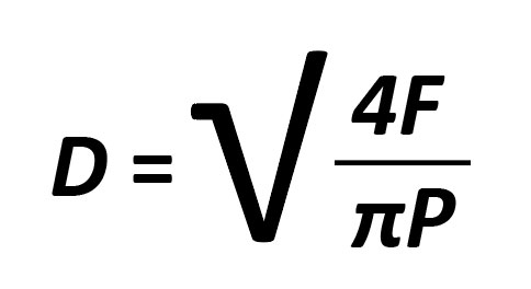
First and foremost, calculate the static force required by your cylinder, which gives us a starting point for deciding upon a bore size. By “static,” I mean essentially the mass of the load you’re moving. The calculation may be simple if your load is lifted vertically by the cylinder, so use this version of the common calculation:
D = Bore diameter F = Force (Mass) P = Pressure Differential
Pressure differential and more
You’ll notice that I used the term pressure differential, which is important to understand, but we’ll get to that in just a second. In the meantime, let’s say we have 500 pounds to lift, and our shop pressure is 100 psi. Running the math, we arrive at an inconvenient bore size of 2.52 in., which is slightly larger than the 2.5 in. standard typical in North America. We’ll have to jump up to the 3.25 in. to accommodate the 500 lb of our load, which likely, we’d do anyway to avoid a marginally capable cylinder.
You must not assume that compressor supply pressure is available in its entirety at the actuator. Even with an FRL located just ahead of the directional valve showing adequate pressure, you must subtract the pressure drop through the valve system and the airlines, and then finally subtract the pressure measured at the cylinder’s opposing work port. This last part is essential because pneumatics is sensitive to pressure drop — in other words, the differential pressure across the piston. (See more on FRLs here).
Many designers prefer to meter out, which means installing the flow control valve oriented to restrict flow exiting the cylinder, which in turn creates back pressure. That back pressure must be subtracted from the work pressure. There is no hard-and-fast number here because the generation of that back pressure depends on the actuator speed, the flow control setting, and the load-induced pressure.
Also, remember that this pressure differential only describes the dynamic properties of the cylinder, where motion itself creates back pressure. A slow-moving or static load is not affected by back pressure from metering out, but since we’re still working through our bore size calculations, let’s use an estimate of 20-40% pressure loss. Although you can install pressure gauges in the work ports of your cylinder, we still need to select our bore size to lift 500 lb, so let’s use the mean figure of 30% reduction from our 100 psi shop air, so we arrive at 70 psi for dynamic loads.
As it turns out, a 3.25 in. bore cylinder can still lift 580 lb with only 70 psi available, and although marginal, should be fine for this application. Acceleration won’t be rapid, but will suit our application. And before you ask, we like to meter out in pneumatics to create some level of “hydrostatic tension,” which offers more stable control.
Construction type
Once we’ve settled on the bore, we can move on to selecting our construction type. The stroke is less critical for this process, so long as the construction type is long enough for your application. Some cylinders are limited in stroke, so if our lift requires more than thirty inches or so, we’ve automatically disqualified many designs.
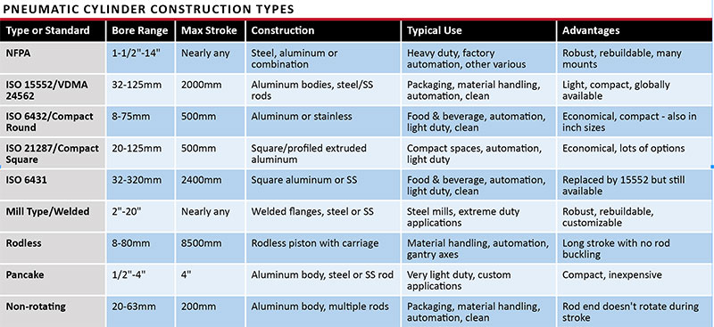
As mentioned in A Designer’s Guide to Cylinders, the construction type is usually a preference, but you need to be aware of each. Although not by any means comprehensive, the following chart provides a list of the most common construction types or standards, the range of sizes and their typical application. Please note that I didn’t survey every single worldwide cylinder manufacturer, so if you’re a manufacturer making products outside these sizes, good for you.
There is some crossover to many of these cylinder types. For example, ISO 21287 with compact, square bodies may be available with non-rotating pistons, although normally such cylinders are unique designs not interchangeable between manufacturers.
When you see “clean” under the Typical Use column, it means a cylinder devoid of construction materials that would emit or outgas during operation, such as grease, assembly lube, or wear particles. They’re typically stainless steel or anodized aluminum, Figure 1, and have more streamlined designs that are easy to clean and resistant to the accumulation of biofilm in crevices or joints. They’re typically used in semiconductor, pharmaceutical, medical, and food & beverage industries.
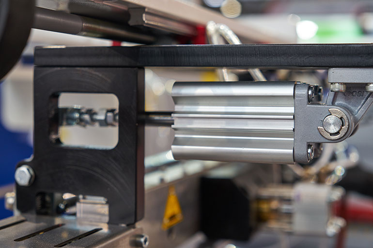
Figure 2. Reed switches are used to sense the piston.
NFPA and mill type cylinders are, as far as pneumatics is concerned, extreme duty options with inherent strength many times what’s required. You’re unlikely to ever break one of these cylinders, so aside from seal kit replacement, these cylinders should last a lifetime. NFPA tie-rod cylinders are industry-standard mounts, and many manufacturers now offer a light-duty “interchange” version with aluminum construction. NFPA cylinders from Company ABC will directly cross to Company XYZ, so don’t be afraid to use your favorite local supplier.
Many of the ISO designations offer standard or common options, such as extruded aluminum profiles that encourage the use of reed switches, which easily slide into a protection position at the side of the cylinder where they can sense the magnetic piston, Figure 2. These profiles make manufacturing simple as the extrusions are cut to either standard or custom lengths and then heads and caps are bolted to either end using threaded studs to seal the cylinder tightly.
The sleeve-nut style studs provide what is essentially a standard cylinder with the option for various common accessories and mounts. The base cylinder could be mounted directly to the four sleeve nuts on the head or cap, or be used to mount one of various clevises, eyes, spherical bearings, head/cap flanges or foot mounts, Figure 3. When selecting your mount of choice, just remember that side load (forces from any direction other than the same axis as the piston) are not your cylinder’s friend and will subject the cylinder to early failure. Ensure your load is guided rather than simply hanging from the rod end.
Figure 3. Mounting is critical, so consider that the base cylinder could be mounted directly to the four sleeve nuts on the head or cap, or be used to mount one of various clevises, eyes, spherical bearings, head/cap flanges or foot mounts.
Cycle time considerations
Once your mount is finalized, you may need to consider the maximum cycle time or velocity. Cycle time factors acceleration and cushioning (deceleration), while maximum velocity is a design limitation of the cylinder, its construction and its seal package. U-Cup seals typically offer quicker breakaway than O-rings or their variants (like quad rings), which are “interference fit,” and subject to higher static friction. Such seals are great for some applications, such as those holding position for longer, but expect a lower velocity rating.
That being said, air cylinders are fast. A U-cup (lip seal) equipped cylinder can expect to perform at over 20 in./sec velocity, while O-ring equipped cylinders might cap at half that speed, although sometimes slower, depending on the construction. In reality, the cylinder will move as fast as it’s being asked to when you throw enough pressure and flow at it, but you risk damaging the cylinder or the machine if you don’t curtail velocity.
When you exceed the recommended velocity of a particular design, the seals are the first to go. More speed means more friction, and the seals will generate heat, leading to rapid wear. You could also see catastrophic slipping, tearing or extruding of the seal when left unchecked. Then comes physical damage, as the piston slams into the head and the cap, or perhaps damages the cushion system or bumpers.
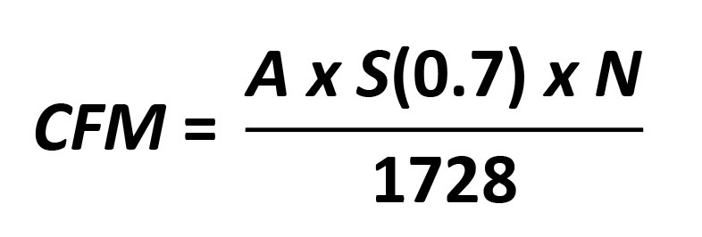
It’s rare that cylinder airflow needs outstrips air supply, especially in industrial manufacturing and automation, where large compressors supply massive airflow on demand. In pneumatics, we first choose our cycle time and then work backwards to calculate the required cfm to do the job. Once you are set on your cycle time (the number of times the cylinder extends and retracts per minute), you can use the following to determine the required cfm. The (0.7) assumes you can only achieve 70% of your cycle time due to acceleration, which is a safe number:
CFM = Cubic feet per minute A = Area of the piston S = Stroke length in inches (0.7 acceleration factor) N = Cycles per minute 1728 = Cubic inches per cubic foot (because we’re using two different units)
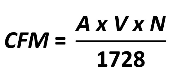
If you’re more concerned with velocity, you can use the following formula. Remember that this is only full speed velocity and doesn’t factor acceleration:
CFM = Cubic feet per minute A = Area of the piston in square inches V = Velocity in inches per second N = 60 seconds in a minute 1728 = Cubic inches within a cubic foot (see note above)
The mount plays a role in pneumatic cylinder performance and reliability, so please reread A Designer’s Guide to Cylinders for specific information on column strength, head versus cap mounts and other important information. The reality is that pneumatic applications are slightly less critical in terms of strength limitations, since they’re responsible for only a fraction of the force required by hydraulics. Still, pneumatics carries far more risk as it pertains to velocity. A small mass accelerated rapidly still has the potential to cause self-induced damage, so be wary of using weaker mounts with high-velocity cylinders.
To recap, the weaker mounts are those with pivot cap mounts, such as rear clevis, rear eye, or perhaps less so, cap trunnion. They extend the column length to more than twice the stroke length and, without a stop tube or oversized rod, can be very weak in long-stroke applications. Even with shorter cylinders, remember that inertia can mimic a heavier load, increasing the risk of detrimental effects such as rod buckling. Don’t let this warning scare you away from these mounts – just be wary. As previously mentioned, pneumatic cylinders are generally strong enough for their force output, so these problems are indeed rare.
The head trunnion is the strongest pivot mount, so consider that or intermediate trunnion for extreme duty applications. Otherwise, most of the fixed mounts should be of sufficient strength for most applications and often come down to your machine’s particular requirements, serviceability and economics. In many cases, such as with pancake, compact, and rodless cylinders, there are only a few mounting options. But when strength does matter, flange mounts are the best, when available.
Special options
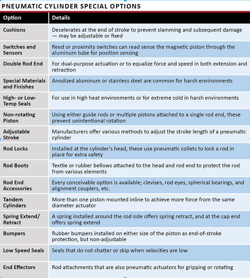
Despite the many standardized cylinder types for pneumatics, their special options list is extensive. They feature modular and simple construction with extruded bodies, sleeve nuts and cast aluminum heads and caps, which does very little to limit their functionality. As you can see from the list of special options in the chart above, you have a plethora of helpful accessories and modifications to suit your machine’s unique requirements.
Most are self-explanatory, but I’ll discuss a few of the more unique choices available to you. Adjustable stroke, for example, seems self-explanatory but could mean several things. There are cylinders with adjustments to modify the stroke partially. For example, a double rod 10 in. stroke cylinder could employ a device on the cap end rod that acts as a stopper. That stopper can be adjusted to a given length of, say, two inches, allowing stroke adjustment anywhere between 8 and 10 in.
Another form of adjustable stroke offers multiple stages of discrete positioning. Imagine two piston-rod assemblies installed into a single cylinder and separated by an intermediate head. There are four ports, one each for the rod and cap port of each assembly. The rear assembly will typically have a shorter stroke, but its piston rod pushes against the piston of the front assembly. Imagine that the front cylinder strokes 10 in. and the rear cylinder strokes 3 in. The single cylinder can position itself from fully retracted, 3 in. extended (rear cylinder) and 10 in. extended (front cylinder) rapidly and precisely.
Rod locks are a great tool to add safety to air cylinders that would typically be inherent to hydraulics using pilot-operated check valves. Because air compresses easily, you can’t simply hold a load safely with PO check valves; but instead, it must be physically blocked by other means. The rod lock is a component mounted to the cylinder head (rod end) that uses a collet to clamp the rod. It is typically used as a safety device to prevent loads from endangering workers, but it can also lock a load in place anywhere along the stroke length when operated at low speed.
Low-speed seals are an important addition to pneumatic cylinders that stroke at low velocity. The effect of “stick slip” causes the piston to chatter as it is stroked at slow speed as the seals grab onto the rod and/or barrel, and then subsequently release with extra energy. Low-speed seals provide more consistent breakaway and allow smooth operation at slow speeds. Sometimes these seals may be used in conjunction with a polished barrel internal diameter.
Pneumatic cylinders are diverse and offer many options for the designer to choose from, and we didn’t even discuss custom designs. With so many choices of construction type and available options, it’s easy to refine your application with the perfect pneumatic cylinder.